The crossover lives in your ear canal: how multi-driver in-ears actually work
Balanced armatures, a capacitor that behaves like a resonant filter, sound tubes measured in millimeters, and a bodypack that quietly rewrites your EQ. A field guide to what's really inside a pair of custom in-ears, and why the seal matters more than the driver count.
Balanced armatures, a capacitor that behaves like a resonant filter, sound tubes measured in millimeters, and a bodypack that quietly rewrites your EQ. A field guide to what's really inside a pair of custom in-ears, and why the seal matters more than the driver count.
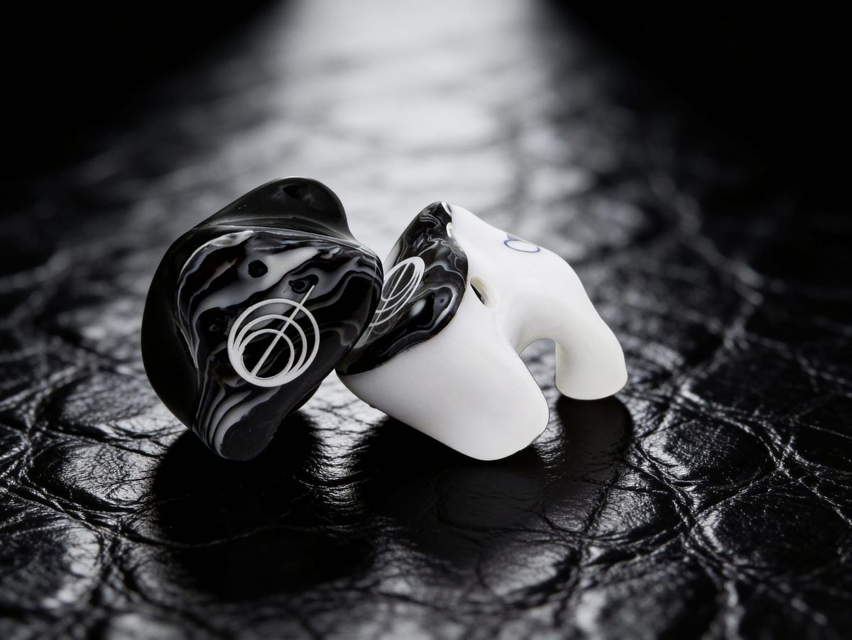
It's 3:40 in the afternoon, and the lead vocalist has new ears. Six drivers a side, custom shells, a faceplate with some kind of abalone inlay that cost more than your first car. She's been raving about them for a week. She listened to the band's last live record on them through the little audio interface in her hotel room and texted the group chat a row of fire emojis.
Now she's on stage, in the same ears, on the same mix you've given her for two years, and she's frowning. "They sound thin," she says. "And kind of shouty? Like the vocal's got a honk in it." She pulls one out, looks at it like it owes her money, and puts it back in.
You check the mix. Nothing's changed. Same snapshot, same channel EQ, same sends. You check the pack. Same pack, same level. You swap in a spare pack. Same complaint. The monitor tech from the other act wanders past, hears the word "honky," and says, without slowing down, "Multi-driver? Check what's driving them." Then he's gone, as monitor techs from other acts always are, a sort of ghost of good advice.
He's right, and the reason he's right is the whole subject of this piece. A multi-driver in-ear isn't one speaker. It's a tiny passive loudspeaker system, with a crossover, with drivers whose impedance swings by a factor of five or more across the band, with sound tubes and acoustic resistors doing the job that cabinets and horns do on a PA, and with the listener's ear canal sealed in as the last acoustic component. The pack is part of the crossover. The ear tip is part of the bass response. Her ear canal is part of the treble.
By the end you'll know why she heard a honk, how to prove it with a multimeter and a resistor, and why the seal is the most important bass control in the rig.
A hearing-aid part walks into a rock show
Start with the driver that made multi-driver in-ears possible: the balanced armature, or BA.
A BA works nothing like the moving-coil driver in a wedge. In a dynamic driver, the voice coil is glued to the cone and moves with it through a magnetic gap. In a balanced armature, the coil stays put. A thin reed of magnetic metal, the armature, runs through the middle of the stationary coil and sits balanced between two permanent magnets. Put current through the coil and the reed becomes magnetized, tipping toward one magnet or the other. A tiny drive rod connects the tip of the reed to a stiff, very light diaphragm, and the diaphragm pushes air out through a small port. The whole thing lives in a sealed metal box a few millimeters long.
Brent Butterworth's piece for SoundStage Solo, built on interviews with Knowles engineers, puts the invention in 1955, when Hugh Knowles developed balanced armatures for the hearing-aid market. Knowles still describes the drivers as originally developed for hearing aids and critical listening. That lineage matters, because hearing aids have the same problem an in-ear has: a tiny transducer, a tiny battery, and a sealed ear canal on the other side.
The first consumer earphone to use it came from a Knowles alumnus. Mead Killion spent 21 years in the Knowles organization working on miniature receivers and microphones under engineering director Elmer Carlson, alongside Hugh Knowles himself (the two co-authored a 1978 paper on the frequency response of broadband receivers). In 1983 he left to start Etymotic Research, and in 1991 Etymotic introduced the ER-4, which the company describes as the first noise-isolating high-fidelity in-ear earphone using balanced armature drivers. So technically, the first BA insert earphone you could buy for music came out of a hearing-science lab, four years before anyone wore one on a rock stage.
The stage version came next. Per the Ultimate Ears and Jerry Harvey histories, in 1995 Alex Van Halen told Harvey that the stage was too loud during rehearsals for the Balance tour. Harvey, working with Karl Cartwright of Westone, built him a custom in-ear with two tiny drivers, one for lows and one for highs, split by a passive crossover. The only low-frequency driver he found that survived a kick drum was a Knowles balanced armature. JH Audio's own company history describes the next step plainly: Harvey combined that bass driver with a high-frequency driver and linked them through a capacitor, and that was the UE-5. Westone designed and built those first Ultimate Ears monitors, and the brand started life as Ultimate Ears by Westone, a detail the later Logitech-era histories tend to skip. Shure's E1 and E5, built with Harvey's help, were billed as the first universal-fit dual-driver monitors, and the UE-10 Pro and UE-11 followed as the company's first three-way and four-way designs.
In-ears weren't new by then, to be fair. ProSoundWeb's history of stage monitoring credits monitor engineer Marty Garcia with building custom-fit earphones for Todd Rundgren in 1982, before he founded Future Sonics. It credits Chris Lindop and Martin Noah's Garwood Communications with the "Radio Station," the first commercially available wireless IEM system, with a bodypack in production in 1987. What Harvey added was splitting the band between drivers, the way we've always done with PA boxes.
Why one driver isn't enough
If a single BA can make bass in a sealed canal and treble anywhere, why stack six of them?
Same reason we don't fly a single 18-inch cone for the whole PA. Each driver has a band it's good at, and outside that band it either runs out of output, rings, breaks up, or beams.
The first limit is in the motor. Knowles engineer Tom Miller, quoted in the SoundStage piece, put it bluntly: a BA is "an inductor and the impedance rises with frequency." The coil is stationary and can have lots of turns, which is great for efficiency and lets the designer pick an impedance, but lots of turns around a metal reed means lots of inductance. Rising impedance means less current, and less current at high frequencies means less force. Designers can trade turns and reed geometry for bandwidth, which is why armature makers sell whole families of parts voiced as woofers, mids and tweeters rather than one magic part.
The second limit is mechanical. The reed, the drive rod and the diaphragm form a little mass-spring system with a resonance, and the output ports and tubes add acoustic resonances on top. A BA voiced for bass is built to put its main resonance and its sensitivity low. A BA voiced for treble is built to stay clean and extended up top.
The third limit is output. Bass in a sealed canal takes volume displacement, and a small diaphragm runs out. The Knowles engineers in that same piece were candid that dynamic drivers have more excursion and bass output, which is why hybrids (a dynamic driver for the lows, BAs for the mids and highs) became common.
So designers split the band, and inherit the same three jobs as any loudspeaker designer: divide the signal, match the levels, and make the outputs sum properly through the crossover region.
One more trick deserves a mention because it explains a lot of spec-sheet driver counts. Two identical armatures wired in parallel see the same voltage, so each moves the same amount of air, and in a sealed canal their volume velocities add. That's up to +6 dB of output at the same drive voltage, and the impedance halves. JH Audio's history describes Harvey wiring multiple small high-frequency armatures in parallel and high-passing them to push the top end out toward 16 kHz. Driver count, in other words, isn't a count of bands. A "twelve-driver" in-ear might be a three-way with four armatures per band, ganged for output and impedance. Next time someone brags about driver count, ask how many ways it is.
The crossover you can't see
On a PA, the crossover is a DSP block with a screen and slope selectors. In a multi-driver in-ear, it's two or three things you'd need a magnifier to see: a few surface-mount capacitors and resistors on a board the size of a fingernail, and a set of plastic or metal sound tubes, some of them with tiny mesh plugs pressed into them.
The textbook first-order high-pass is a capacitor in series with a resistive load. The corner sits where the capacitor's reactance equals the load resistance, f = 1 / (2πRC), and above that point the response flattens out. Below it, the response falls at 6 dB per octave. Feed a 6-ohm resistor through a 4.7 µF capacitor and the corner lands at 1 / (2π × 6 × 4.7 × 10⁻⁶), about 5.6 kHz. That's the dashed gray line in Fig. 1.
But a BA is not a resistor. It's a resistor in series with an inductor. Put a capacitor in series with an inductor and you've built a series resonant circuit. At the frequency where the capacitor's reactance and the inductor's reactance cancel, the current through the branch peaks, and the voltage across the driver can rise above the input. The "6 dB per octave" cap has quietly become a second-order high-pass with a resonant bump.
In the model above, a 4.7 µF cap feeding a tweeter armature (6 ohms of resistance and 0.12 mH of inductance, numbers chosen to be in a realistic range, not copied from any specific part) produces a bump of about +2.7 dB near 8 kHz. Add a 3.3-ohm resistor in series and the bump disappears. Add 10 ohms and the bump is gone, the whole top end drops, and the slope gets gentler. That's why in-ear crossovers have resistors that seem to waste power: they're damping the resonance between the crossover cap and the driver's own inductance, and padding the tweeter level down to match the woofer. Same jobs that the L-pad and Zobel do in a passive PA crossover, at about a thousandth of the size.
The woofer side is often handled differently. An inductor big enough to low-pass a BA woofer would be enormous at this scale, so designers lean on the woofer's own rising inductance and then filter its acoustic output with the tube and damper.
The acoustic half of the crossover looks less like loudspeaker design and more like plumbing.
A sound tube is an acoustic transmission line. Its length and diameter set where it resonates and how much it attenuates. A narrow, long tube attenuates the highs; it behaves like an acoustic low-pass. Shure markets the SE846 as having a low-pass filter that gives it "the deep low-end performance of a true subwoofer," which is the same idea taken further: use the acoustic path itself to strip the top off the woofer's output so it can't muddy the mids.
Then there are dampers. Knowles sells tiny cylindrical acoustic resistors, little mesh-and-plastic plugs about 2 mm across, that press into a tube or port. They're specified in acoustic ohms and color-coded. One parts listing for the Knowles BF-1860, for instance, gives it as brown, 1,000 ohms, about 2.08 mm in diameter. An acoustic resistance does to a tube resonance what a resistor does to an LC resonance: it soaks up energy at the peak and lowers its Q. JH Audio's history describes Harvey applying damping material to the low driver to get what he called a convincing pseudo-sub-bass and a proper three-way crossover. Change the damper and you change the tuning, which is why some universal in-ears ship with swappable nozzle filters. Those aren't a gimmick. They're a crossover adjustment you can do with tweezers.
So a real multi-driver in-ear crossover is a hybrid: electrical high-passing with caps, padding and damping with resistors, and acoustic low-passing and peak control with tubes and dampers. The good news is that it's all passive, so it's all predictable. The bad news is that it's all passive, so it all depends on what's on either side of it. On one side, the pack. On the other, the ear.
Your bodypack is part of the crossover
Every amplifier output has some internal impedance in series with it. On a well-designed power amp driving loudspeakers it's a tiny fraction of an ohm, which is why we talk about damping factor in the hundreds. On headphone outputs it's all over the map. Sound on Sound reported on Sonarworks measurements of 170 headphone outputs and found most landed somewhere between 1 and 10 ohms, with an RME Fireface UCX at 30 ohms, a Fireface UFX II at 2, and a Schiit Magni 3 under 0.3. SOS also notes that IEC 61938 (1996) specified a 120-ohm headphone source impedance, which was never adopted. Thank goodness.
That source impedance forms a voltage divider with the earphone. The voltage that actually reaches the earphone is:
V_load = V_source × Z_load / (Z_load + Z_out)
If Z_load were constant, this would just be a fixed level drop, and you'd turn the pack up a hair and move on. The trouble is that a multi-driver in-ear's impedance isn't constant. Not even close.
Fig. 2 shows the impedance of a modeled two-way BA earphone: a woofer armature in parallel with a tweeter armature that's fed through a cap and a small resistor. In the bass it sits around 19 ohms. As the woofer's inductance and mechanical resonance kick in, it climbs to about 61 ohms near 660 Hz. Then the tweeter branch comes in through its capacitor, the impedance falls, and it bottoms out at about 8.8 ohms near 6.8 kHz before rising again. That's a seven-to-one swing. It's a model, not a product, but it isn't an exaggeration. NwAvGuy's well-known measurements of the Ultimate Ears SuperFi 5 (a 21-ohm-rated dual-BA design) showed it sitting at 21 ohms below about 200 Hz, rising to nearly 90 ohms around 1.2 kHz, and dropping below 10 ohms around 11 kHz. Archimago measured a Shure SE846 dipping to 5.5 ohms around 5 kHz. Sound on Sound reports a Shure SE535 dipping to about 9 ohms.
Now run that through the voltage divider.
With a 0.5-ohm source, the earphone sees essentially the same voltage at every frequency: about 0.4 dB of total variation in our model. Fine. With a 10-ohm source, the divider takes 1.3 dB off at the 61-ohm peak (61 / 71) and 6.6 dB off at the 8.8-ohm dip (8.8 / 18.8). The difference, 5.3 dB, is now an EQ curve that nobody dialed in: a lift in the low mids relative to the top, and a scoop right in the presence and air region. At a 43-ohm source the swing is nearly 11 dB.
That's our honk. If her hotel interface had a near-zero output impedance and the pack's headphone output is somewhere around 10 ohms, she's hearing more low-mid and less 5 to 8 kHz on stage than she heard in the hotel room. Low-mid up and presence down reads as "thin and honky" at once, which sounds contradictory until you look at the curve. Nobody touched an EQ.
This isn't hypothetical. NwAvGuy measured the SuperFi 5 with a 43-ohm source and saw about 12 dB of total response variation, and about 6 dB with a 10-ohm source, much of it as a sharp notch near 10 kHz. Sound on Sound reports a maximum deviation of 7.5 dB on the SE535 between a 1-ohm source and a 50-ohm source. Some manufacturers use the effect on purpose. Headphones.com notes that the Truthear x Crinacle Zero:Red ships with a 10-ohm adapter to give a controlled bass lift of about 3 dB.
The usual rule of thumb, popularized by NwAvGuy, is to keep the source impedance below one-eighth of the headphone's impedance. For a 16-ohm earphone that's 2 ohms or less. But note the catch: one-eighth of what? A spec sheet gives a nominal impedance, often measured at 1 kHz. For a multi-BA in-ear, the number that matters is the minimum, because that's where the divider bites hardest. If the minimum is 5.5 ohms, one-eighth of that is under 0.7 ohms. Very few wireless bodypacks publish their headphone output impedance at all. So you measure it.
Here's how, with a multimeter, a resistor and a sine wave. Play a 1 kHz tone through the pack. Measure the AC voltage at the headphone output through a breakout cable with nothing else connected. Call that V_open. Now put a known resistor across the output, say 33 ohms, and measure again. Call that V_load. The output impedance is:
Z_out = R_load × (V_open / V_load − 1)
Worked example: V_open = 1.00 V, V_load = 0.80 V with 33 ohms. Z_out = 33 × (1.25 − 1) = 8.25 ohms. Keep the level low enough that the output isn't clipping or current-limiting into the resistor, and do it at a couple of frequencies to be sure. Your meter's AC accuracy at 1 kHz is usually fine; at 10 kHz cheap meters start to lie, so stay low.
If the answer is a handful of ohms and the artist is on a multi-BA in-ear with a deep dip, you can EQ for it on that mix (knowing the fix only applies to that earphone on that pack), try a hardwired amp with a lower output impedance, or pick earphones designed with a flat impedance curve, which Headphones.com notes some makers now do. Ask for the impedance plot before an artist commits to a thousand-dollar pair. The maker has one.
One more thing. Output impedance also affects electrical damping, and NwAvGuy's one-eighth rule was partly about keeping enough of it. But the big lesson is simpler: an in-ear's published frequency response assumes some source. If your source isn't that source, the earphone you're mixing on isn't the earphone in the brochure.
Millimeters matter: tubes, timing and the notch
On a PA, we time-align drivers because their acoustic centers sit at different distances from the listener. A few centimeters of offset between a compression driver and a woofer cone is enough to tilt the lobe and dig a notch through the crossover. A loudspeaker system the size of a fingertip isn't immune. The offsets are smaller, but so are the wavelengths that matter.
In a multi-driver in-ear, each driver's output travels to the nozzle through its own path: out the driver's port, down a tube, through a damper, and into a shared bore. If the woofer's path is longer than the tweeter's, the woofer's sound arrives later. Where both drivers contribute at similar level, which is the crossover region, that delay turns into comb filtering exactly as it does with two boxes on a stage.
The arithmetic is the same arithmetic we use for delay towers. Time offset is path difference over the speed of sound. At 343 m/s, a 10 mm path difference is 10 / 343,000 seconds, about 29 microseconds. Two equal-level signals with that offset cancel completely where the delay equals half a period: f_null = 1 / (2Δt), or, the same thing, c / (2 × path difference). For 10 mm, that's about 17 kHz. For 20 mm, about 8.6 kHz.
A 17 kHz null sounds harmless, and above most crossover regions it is, because by then the woofer has been filtered well out of the way. But move the crossover up into the upper mids or presence region and push the path difference to a couple of centimeters, and the first null lands in a place you'll hear. The Knowles engineers in the SoundStage interview said almost exactly this: the woofer and tweeter need to be in phase through the crossover region, and if they aren't, you can get a cancellation notch around 6 to 8 kHz. That's real estate where sibilance and cymbal definition live.
Phase isn't only about path length. Every filter, electrical or acoustic, adds phase shift, and two drivers coming out of different filters with different slopes can be out of phase at crossover even with identical path lengths. That's the in-ear version of the Linkwitz-Riley summing problem we went through in the PA crossover piece: the filters have to be designed so their phases line up where their levels overlap. JH Audio introduced its "freq|phase" waveguide in 2012 aimed at exactly this. You don't need to buy the marketing language to buy the physics.
Tubes also have resonances of their own. Any tube with a length L that's close to a quarter or a half wavelength will resonate, and a sound bore of a couple of centimeters puts those resonances in the upper treble. A 20 mm length is half a wavelength at about 8.6 kHz. Real tube resonances depend on what's at each end, so treat that as order-of-magnitude. It's still the reason dampers exist, and why in-ear measurements so often show narrow treble peaks that move when you swap a nozzle filter.
And then, as the last tube in the system, there's the ear canal itself.
The seal is the bass control
This is the part that surprises people most, and it's why a hearing-aid driver could handle a Van Halen kick drum.
When a loudspeaker radiates into a room, the pressure it makes at a distance depends on how fast its diaphragm accelerates. To keep the same output an octave lower, the diaphragm has to move four times as far.
A sealed ear canal is not a room. It's a tiny closed volume. The ear canal is about 25 mm long and about 7 mm across, according to the anatomy references (OSHA gives 26 mm), so its volume is roughly π × (3.5 mm)² × 25 mm, a little under 1 cm³. When the canal is sealed and the wavelength is much larger than the canal, which is true for all of the bass and most of the mids, the air in that volume behaves like a spring. Push the diaphragm in by a tiny volume ΔV and the pressure rises by about ρc² × ΔV / V. Pressure depends on displacement, not acceleration. Below the driver's own resonance, where its motion is controlled by its stiffness, a constant drive voltage gives a constant displacement at every frequency. Constant displacement into a sealed volume gives constant pressure. Flat bass, down to almost nothing, from a diaphragm a few millimeters across.
That's the magic, and it's also the trap. The flat bass depends entirely on the volume being sealed. Open a leak, through a poor fit, a shallow tip, a jaw that moves when the singer sings, or a bit of hair, and the leak acts as an acoustic resistance in parallel with the canal's compliance. Below a corner frequency set by those two, f_c = 1 / (2πRC), air just squirts out of the leak instead of compressing, and the pressure falls at 6 dB per octave. The Wikipedia article on the occlusion effect makes the same point from the other side: an incomplete seal has a similar effect at frequencies below the Helmholtz resonance the system forms.
With a good seal, the corner sits down at a few hertz and you never hear it. With a small leak, it moves up to 40 Hz or so and the kick drum loses its weight. With a bad fit, the corner can sit at a couple of hundred hertz. At that corner, the model in Fig. 5 is down 12.3 dB at 50 Hz.
Now think about what the artist does about that. They don't say "I have a leak with a 200 Hz corner." They say "I need more of me and more bass," and you, or they, turn the whole mix up. Getting that 12 dB back by turning up means sixteen times the acoustic power across the entire band, not just in the bass. We'll come back to that number in the next section, because it's the most important worked example in this piece.
Sealing the canal changes the treble too. An open ear canal is a tube open at the outer end and closed at the eardrum, which makes it a quarter-wave resonator. For a 25 mm canal, c / 4L is 343 / (4 × 0.025), about 3.4 kHz. OSHA's description of the ear gives about 10 dB of gain at the eardrum around 3,300 Hz from that resonance, and 10 to 15 dB of boost in the 2 to 4 kHz range from the head, pinna and canal together. Every sound you've ever heard in open air arrived with that boost baked in. Your brain treats it as normal.
Seal the canal with an in-ear and that resonance is gone. What's left is a shorter tube closed at both ends, the earphone tip on one end and the eardrum on the other, which resonates at a half wavelength instead. If the tip sits 13 mm into a 25 mm canal, the remaining 12 mm resonates near 343 / (2 × 0.012), about 14 kHz. Real eardrums aren't rigid walls and real canals aren't straight cylinders, so treat that as a rough estimate. But the direction is right: a sealed in-ear loses the open-ear 3 kHz gain, and gains a new resonance higher up whose frequency depends on how deep the tip sits.
That's why in-ear target responses don't look flat. The Harman research group (Sean Olive, Todd Welti and Omid Khonsaripour) ran a series of studies on in-ear preferences. In 2016 they had trained listeners adjust a second-order low-shelf filter to find the preferred bass level, with tests for loudness normalization and leakage. In 2017 they had 71 listeners rate 30 in-ear models against a hidden reference equalized to their in-ear target, and found that the further a model deviated from the target response, the less listeners liked it. The details sit behind the AES paywall and are still argued over, especially as newer ear simulators like the B&K 5128 change how in-ears get measured. The principle isn't argued over: a well-tuned in-ear is not flat at the eardrum, because your ear never was.
It's also why the same in-ear sounds different in two people's ears, or with two different tips. Deeper insertion pushes that residual-canal resonance up; shallower pulls it down toward where it sounds sharp.
And insertion depth matters to singers for a second reason: the occlusion effect. When you seal your ear canal and talk, low frequencies from your own voice conducted through your skull and jaw get trapped in the canal and sound boomy. Kichol Lee's 2011 study at Virginia Tech found the occlusion effect at 500 Hz was on average 11.2 dB greater with shallow earplug insertion than with deep insertion. That's eleven decibels of "my voice sounds weird" that has nothing to do with the mix. Deeper fits, which customs give you, usually help. When a vocalist on universals complains that her own voice sounds muffled and boomy no matter what you do with her vocal channel, check the fit before you reach for the EQ.
So the ear tip and the shell are not accessories. They're the final acoustic components of the system: the seal sets the bass, the insertion depth sets the treble resonance and the occlusion, and none of it shows up on a spec sheet.
Sensitivity, hiss and the dose
Balanced armatures are efficient, and multi-BA in-ears often more so. Sensitivity is quoted either in dB SPL per milliwatt or, more usefully for a voltage-driven output, in dB SPL per volt. Sound on Sound gives the Shure SE535 at 134 dB/V; Archimago lists the SE846 at a rated 135.6 dB/V and measured a six-driver Noble Khan at 131 dB/V. For comparison, SOS lists the Sennheiser HD650 at 105 dB/V. That's about 30 dB of difference between a popular studio headphone and a popular stage in-ear.
Worked example. If the in-ear makes 134 dB SPL with 1 V across it, how much voltage gets you to a fairly loud 100 dB SPL? You need 34 dB less, so 1 V × 10^(−34/20), which is about 20 mV. Twenty millivolts. Your bodypack is spending most of its life putting out a few millivolts.
Now flip it around. Suppose the pack's output has a residual noise floor of 10 µV. That's 100 dB below 1 V, so through a 134 dB/V earphone it becomes 134 − 100 = 34 dB SPL of hiss, right at the eardrum, during every quiet moment between songs. Plug a 105 dB/V headphone into the same output and that hiss falls to 5 dB SPL, inaudible. Same pack, same noise, 29 dB difference in how much the artist hears it. That 10 µV figure is an illustration, not a measurement of any particular pack, but the arithmetic is why super-sensitive multi-BA customs have a reputation for being "hissy" on some systems. The earphone isn't noisy. It's being honest about the noise it's given.
Two rulebooks show up in this conversation. NIOSH, the US research agency, sets a recommended exposure limit of 85 dBA averaged over an eight-hour day, and recommends halving the exposure time for every 3 dBA increase. That 3 dB "exchange rate" is the equal-energy rule: 3 dB more is twice the power, so half the time. OSHA, the US regulator, sets a permissible exposure limit of 90 dBA for eight hours with a 5 dB exchange rate, which is far more lenient as levels rise. OSHA's own noise page spells out the gap: at 100 dBA, OSHA allows two hours, while NIOSH recommends less than 15 minutes.
Now go back to the leak. The artist with the poor seal lost 12 dB of bass and turned the whole mix up 12 dB to get it back. On the NIOSH curve, 12 dB is four 3 dB steps, so the allowable time drops by a factor of sixteen. If her mix had been sitting at 88 dBA, which NIOSH allows for about four hours, it's now sitting at 100 dBA, and she has a 15-minute daily budget. For a 90-minute show. That isn't a monitor mix problem or an earphone problem. It's a fit problem, and it's the single most practical reason to care about everything in the last section.
Isolation is the other side of the same coin. The point of in-ears is that the seal also keeps the stage out. Shure, for instance, claims its sound-isolating designs block up to 37 dB of outside noise. If the stage is at 105 dBA and the earphone gives 25 dB of isolation, the leakage is around 80 dBA and the mix can sit a sensible margin above it. If the seal is poor and the isolation is 10 dB, the leakage is 95 and the mix has to fight its way above that, straight into the steep part of the NIOSH curve. A good seal buys bass, isolation and hearing time at once.
One caveat: these are workplace rules for averaged daily exposure, and SPL in a sealed canal isn't directly comparable to a dBA reading at the mix position. Use the numbers to understand how fast the budget goes, not as a dosimeter.
What you can take back to the desk
Ask for the impedance curve, not the impedance. A multi-driver in-ear's nominal impedance tells you almost nothing. The minimum tells you how hard the source impedance will bite. If the maker won't share a plot, assume a deep dip somewhere in the treble.
Measure your packs. Open-circuit voltage, loaded voltage, a known resistor, and Z_out = R × (V_open / V_load − 1). Ten minutes per pack model. Write the number on tape inside the case lid. If it's more than about one-eighth of the earphone's minimum impedance, expect audible tonal changes, and expect them to differ between the artist's hotel interface and your stage rig.
When new ears sound different on stage, suspect the source before the mix. Low mids up and a scoop somewhere in the 5 to 10 kHz region is the classic signature of a multi-BA in-ear on a higher-impedance output.
Driver count is not band count. Ask how many ways it is. A four-driver three-way and a twelve-driver three-way are both three-ways. The extras are usually parallel armatures for output and impedance, not extra bands.
Nozzle filters are crossover adjustments. If an artist's universal in-ears came with swappable filters, those filters change the acoustic damping and therefore the tuning. Note which ones are fitted, and don't let them get swapped between shows without someone writing it down.
Treat the seal as the bass knob. If the artist is asking for more of everything, check the fit first. A leak can cost a dozen decibels at 50 Hz, and the fix for that is not 12 dB more mix. Check tips, check insertion, check whether the seal breaks when they sing wide.
Mind the occlusion effect for singers. "My voice sounds boomy" is often the canal, not the channel. Deeper fits help; EQ won't fix what the skull is doing.
Respect the sensitivity. A 134 dB/V earphone turns 20 mV into 100 dB SPL and turns microvolts of noise into audible hiss. Set gain structure so the pack's volume control sits in a sensible range, and keep an eye on artists who run their packs nearly off.
Do the dose arithmetic out loud. Every 3 dB is half the time on the NIOSH clock. Twelve dB of "turn it up, I can't hear the kick" is a factor of sixteen. Artists respond to that number better than they respond to "you should probably turn down."
And back to our vocalist with the honk. You measure the pack: about 10 ohms. You ask the in-ear maker for the impedance plot: a dip to 8 ohms in the presence region. You swap her to a hardwired amp for the next show and the honk is gone, and she texts the group chat a row of fire emojis again. The mix never changed. The loudspeaker system she's wearing did, because the thing driving it changed. Now you know where to look.
Above the Fader
Sauce
- Knowles: What is balanced armature?
- SoundStage Solo: Balanced armatures, why you might (or might not) want them, Brent Butterworth
- Wikipedia: Jerry Harvey (inventor)
- Wikipedia: Ultimate Ears
- Wikipedia: Westone
- Etymotic Research: About us
- Canadian Audiologist: Interview with Dr. Mead C. Killion
- JH Audio: company history
- ProSoundWeb: Hear at last, a history of stage monitoring
- Sound on Sound: Phones and ohms, Rudolfs Putnins
- NwAvGuy: Headphone and amp impedance
- NwAvGuy: Headphone impedance explained
- Archimago: Headphone impedance, output impedance and IEM measurements
- Headphones.com: Output impedance explained, Caleb Loo
- Knowles BF-1860 acoustic damper listing
- Shure SE846 product page
- OSHA: Occupational noise exposure
- NIOSH: About noise and occupational hearing loss
- Wikipedia: Ear canal
- Wikipedia: Occlusion effect
- Lee, K. (2011): Effects of earplug material, insertion depth, and measurement technique on hearing occlusion effect, Virginia Tech
- Olive, Welti, Khonsaripour (2016): The preferred low frequency response of in-ear headphones, AES
- Olive, Welti, Khonsaripour (2017): A statistical model that predicts listeners' preference ratings of in-ear headphones, part 1, AES
- SoundGuys: Harman research targets the B&K 5128